LPILE
2022
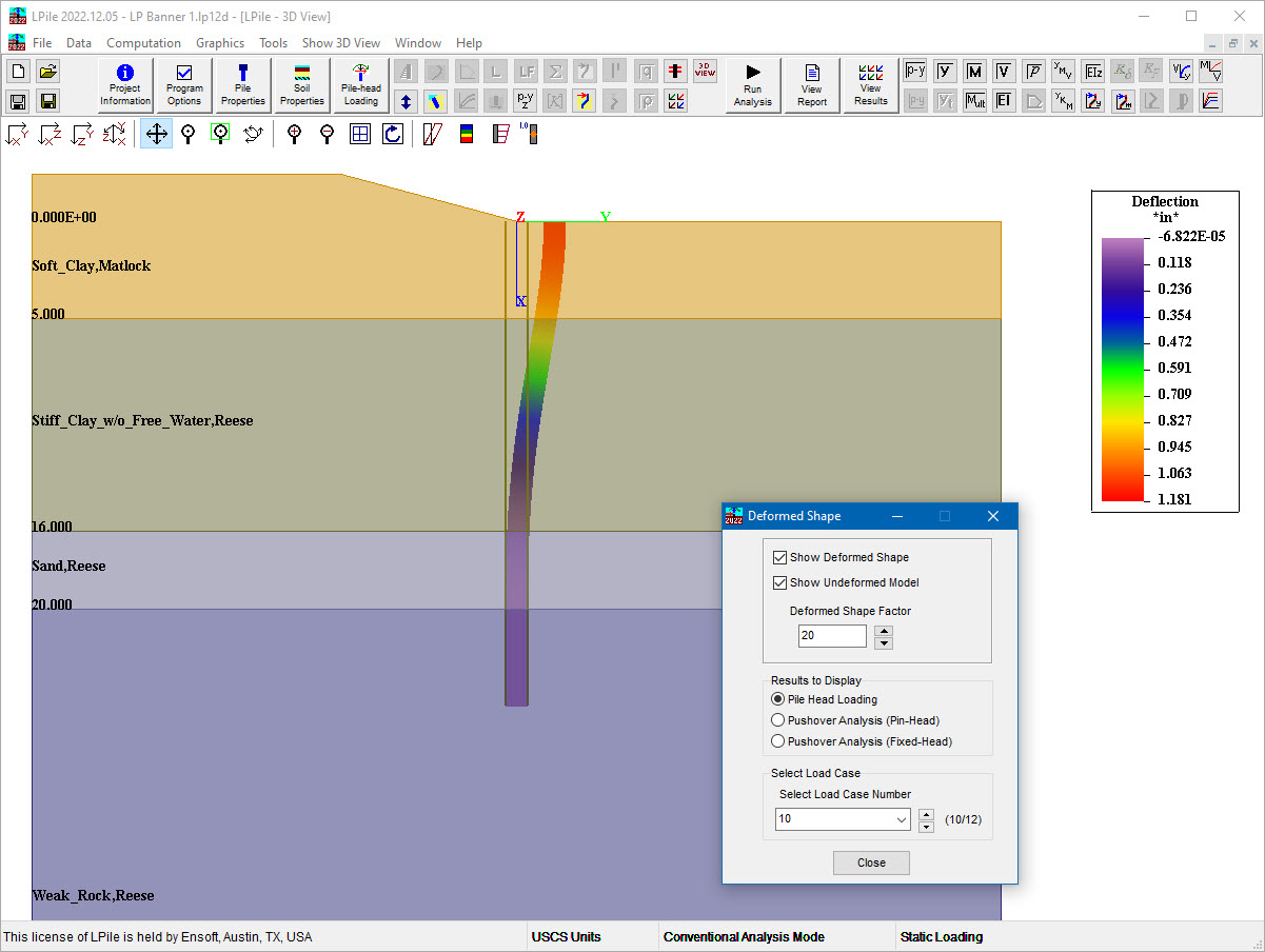
LPILE is a special-purpose and internationally recognized computer program based on rational procedures for analyzing a pile under lateral loading using the p-y method. LPILE solves the differential equation for a beam-column using a finite difference approach. The program computes deflection, bending moment, shear force and soil response over the length of the pile.
Nonlinear lateral load-transfers from the foundation to the soil is modeled with p-y curves generated internally using published recommendations for various types of soils, or user-specified p-y curves. Specialized procedures are also available for computing p-y curves for layered soils and rocks.
Since the first commercial release release dating back to 1986, LPILE has been continuously developed and improved to meet user needs and incorporate state-of-the-art procedures from published technical research.


Various built-in p-y curves including:
The user may define multiple pile sections with elastic and/or nonlinear bending properties. This allows a designer to see the effects from say cutting off part of the reinforcing steel at the lower sections of a drilled shaft. Wide selection of built-in and configurable cross sections (variable with depth as necessary) such as:
Model piles as either vertical or battered and consider sloping ground surfaces by adjusting internal modification factors.
Several pile lengths may be automatically checked by the program in order to help the user produce a design with an optimum pile penetration. For this purpose, users can evaluate the curve of pile-head deflections versus pile length.
The user may observe the nonlinear values of the foundation stiffness matrix.
Users may input lateral load test results for direct graphical comparison to computed pile response from LPILE. This is helpful for calibrating input properties to optimize pile designs.
Bundled bar arrangements can be modeled in LPILE for 2-bar and 3-bar bundles.
Specify user-defined multipliers to adjust for pile group effects in closely-spaced piles or to reduce pile response in liquefied layers for sustained long-term loading or seismic conditions.
Consider soil-layering effects by adjusting p-y curves. Specify nonlinear resistance curves to consider tip shear resistance provided at the base of large diameter drilled shafts or short piles.
See response of pile under lateral or bending moment, or specify lateral displacement or rotation at pile-head.
Specify distributed lateral loading along the length of the piles and shafts, and compute the response of piles up to 50 different user-defined load cases. For LRFD based analyses, user can specify the load factors or LPILE can choose them.
The user is able to input a profile of soil movements versus depth as additional loading on the pile. The movements of the soil may be produced from any action that causes soil movements, such as movements due to slope instability, lateral spreading during earthquakes, and seepage forces.
LPILE comes equipped with electronic copies of detailed user's manual and a technical manual, as well as over 50 examples and input files. Download and view the examples and input files with LPILE running in Demo mode.
Consider p-Δ effects and buckling and determine the nominal bending. LPILE is quick, with the average analysis taking only a few seconds.
Four values (K22, K23, K32, and K33) of a typical 6x6 matrix for foundation stiffness may be generated by the program for a range of loading or deformation. These values can be used to model nonlinear foundation springs in the analysis of the superstructure.
LPILE has the capability to perform push-over analyses and can study the pile behavior after the development of plastic hinges (yielding). New control features have been added for Pushover Analyses and users can see output plots of Shear vs Pushover Deflection and Bending Moment vs Pushover Deflection.
Lateral deflection, pile bending moment, shear force, mobilized sectional properties, or curvature of piles under each load case, and more are outputted for each model.
Detailed printer-friendly generated output files report all influencing parameters used for computation of internally generated p-y curves, deflection, bending moment, shear, mobilized soil reaction, moment-curvature, interaction diagram, and more, with the option to to export all results into Microsoft Excel.